The following story are from thuleforum.
This is the best story I have found about the missile launches in Thule
NIKE MISSILE SITES, AT THULE AB, GREENLAND
NIKE MISSILE SITES THE UNOFFICIAL HISTORY OF A, B, C, AND D LAUNCH AT THULE AB, GREENLAND
THULE AB, GREENLAND 1959-1965
By MSgt Edward L. Hilton 12 SWS/MAO 1999-2000
INTRODUCTION
The advent of the world''s first land-based antiaircraft guided missile system, coupled with the growing threat of atomic attack by manned enemy bombers, brought significant changes in both the continental air defense structure and the Army''s antiair missions and organization.
The first came on 1 September 1954, when the Army Antiaircraft Command and its sister elements in the Air Force and Navy were combined into a single organization, the Continental Air Defense Command (CONAD), directed by the Joint Chiefs of Staff and located at Colorado Springs, Colorado.
This was followed, in 1957, by a realignment of the roles and missions of the three CONAD components.
The Army''s air defense role was expanded by the assignment of longer ranges and broader coverage for its antiair missiles.
Under CONAD, the Army was charged with point air defense by missiles fired from the ground at aerial targets not more than 100 miles away.
The Air Force was responsible for manned interceptors, area defense, and missile ranges over 100 miles, and the Navy for sea approaches.
Point defense included those geographical areas, cities, and vital installations that could be defended by missile units, which received their guidance information from radar located near the launching site.
It also included the responsibility of a ground commander for the air protection of his forces.
On 21 March 1957, the Army Antiaircraft Command was renamed the U. S. Army Air Defense Command (ARADCOM), a designation that more clearly defined the "all missile" role of the command. In September 1957, the North American Air Defense Command (NORAD) was formed to combine the air defense capabilities of Canada and the United States under one commander-in-chief, who also headed CONAD. The missile units of ARADCOM and its sister services were placed under NORAD''s operational control. In the United States, NORAD reported to the Joint Chiefs of Staff; in Canada, to the Chief of Staff Committee. The unified structure of NORAD gave the continental air defense system true "defense in depth." This strategy combined the dimension of distance with a variety of modern weapons, ready to meet and engage the enemy along the full range of his attack. While the ability to deliver a retaliatory blow remained the principal deterrent against atomic attack, improved air defenses heightened the value of the deterrent and promised to exact a high cost in any attack by manned enemy bombers.
The NIKE AJAX fulfilled the mission for which it was designed and for several years served as the free world''s primary air defense. However, even before deployment of the AJAX, if was realized that the weapon system possessed certain performance limitations that would prevent it from engaging formations of the faster, higher-flying jet aircraft. Though superior to conventional antiaircraft artillery against single targets at supersonic speeds and high altitudes, the AJAX target tracking radar was limited in the resolution of aircraft in formation and therefore ineffective against mass air attack. This radar had a tendency to wander from plane to plane in the attacking formation, with the result that the missile would pass between two targets and burst where no damage would be done. In view of the performance limitations inherent in the NIKE AJAX guided missile system and the rapid advancements in aircraft altitudes, speeds, and nuclear payload capabilities, the Ordnance Corps, in 1952, had begun feasibility studies of an improved air defense system that would be capable of countering the new aerial threat. These studies culminated in the second-generation Basic NIKE HERCULES system, which began replacing the NIKE AJAX in 1958; the Improved HERCULES system, which became operational in 1961; and the HERCULES Antitactical Ballistic Missile system, which became available in 1963.
WHY NIKE?
During the years immediately following the Korean War, the "ack-ack" of conventional antiaircraft artillery guns gradually gave way to the "ack-track-smack" of the NIKE AJAX, the first land based air defense guided missile system to be tactically deployed in the United States and allied countries. The conversion from guns to guided missile artillery began on 20 March 1954, when the first combat-ready NIKE AJAX battalion was tactically deployed at Fort Meade, Maryland, in the Washington-Baltimore Defense Area. Although conventional antiaircraft gun units continued to play important roles in augmenting the protection provided by NIKE AJAX battalions, the NIKE had already outnumbered them as early as December 1956.
NIKE AJAX batteries were installed around strategic sites in the Continental United Stares (CONUS) and overseas. Each battery was an integrated air defense guided missile unit that, with its command guidance system, could engage one aircraft at a time while maintaining continuous surveillance of all targets within the effective range of the system. Its primary mission was the destruction of long-range bombers having speeds of up to 1,100 mph. The maximum practicable range was 45,700 meters against aircraft at altitudes of up to 60,000 feet, but targets could be identified as far away as 128,000 meters, and a missile could be launched when its target was 75,000 meters from the battery.
The NIKE AJAX had a command-type guidance system with acquisition radar on the ground that detected targets and furnished initial data on their positions to a target tracking radar, also on the ground. The latter radar obtained accurate information on the path of the target and transmitted it to the control computer, while at the same time a ground-based missile tracking radar furnished the computer with data on the position of the missile. The computer generated guidance-command signals, which were transmitted to the missile-borne guidance and control system by way of the transmitter of the missile tracking radar. The AJAX missile was first propelled by a booster motor that burned a cast, doublebase solid propellant. The booster was jettisoned after burnout, and flight was sustained by a liquid propellant motor with jet engine fuel and red-fuming nitric acid for the oxidizer. The missile carried a conventional high-explosive Warhead.
The NIKE AJAX fulfilled the mission for which it was designed and for several years served as the free world''s primary air defense. However, even before deployment of the AJAX, it was realized that the weapon system possessed certain performance limitations that would prevent it from engaging formations of the faster, higher-flying jet aircraft. Though superior to conventional antiaircraft artillery against single targets at supersonic speeds and high altitudes, the AJAX target tracking radar was limited in the resolution of aircraft in formation and therefore ineffective against mass air attack. This radar had a tendency to wander from plane to plane in the attacking formation, with the result that the missile would pass between two targets and burst where no damage would be done. In view of the performance limitations inherent in the NIKE AJAX guid ed missile system and the rapid advancements in aircraft altitudes, speeds, and nuclear payload capabilities, the Ordnance Corps, in 1952, had begun feasibility studies of an improved air defense system that would be capable of countering the new aerial threat. These studies culminated in the second-generation Basic NIKE HERCULES system, which began replacing the NIKE AJAX in 1958; the Improved HERCULES system, which became operational in 1961; and the HERCULES Antitactical Ballistic Missile system, which became available in 1963.
World War II generated a tremendous leap in military technology, especially in strategic bombers, air-breathing missiles like the German V-I, ballistic missiles like the German V-2, jet-powered airplanes and atomic bombs. These advances in technology, combined with the Soviet Union''s threat of world domination in the post-war years, caused the United States to take action to prevent yet another war this century. And if deterrence failed, the objective was to limit the damage to its citizenry and war-making capability.
During the final months of World War II, several major defense contractors studied the likelihood that evolving technologies could produce guided missiles to intercept bombers and surface-to-surface missiles. One of these projects, called NIKE after the Greek goddess of victory, would grow to a full deployment of more than 240 missile sites in the United States. Operating these sites were nearly 45,000 active duty and National Guard soldiers. ARADCOM controlled these missiles and antiaircraft guns and a vast network of command centers to communicate with them.
Threat-wise, the Soviet Union dominated the scene; its bombers and ballistic missiles held center stage in decisions made to deploy defensive systems. Nationally, the focus will be on key decisions made in Washington. Administrations from Truman through Ford made tough calls in allocating resources within the nation and the military. Budgets, taxes and competing domestic needs caused decisions on deploying systems to be politically challenging, to say the least.
Within the military, the services interacted to accomplish the air defense mission. Actions by the Department of Defense (DOD), the North American Air Defense Command (NORAD), and the other services, especially the Air Force, included a competition for resources that developed into inter-service rivalry. Yet the rivals cooperated in many ventures to ensure national defense. The Air Force was responsible for "Area Defense", and the Army (ARADCOM) was responsible for "Point Defense".
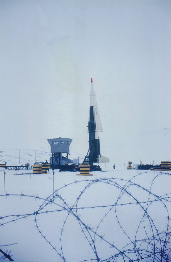
ARADCOM, whose motto was "Vigilant and Invincible", was the last line of defense against attacking enemy aircraft. When deterrence became a part of the United States'' national strategy, ARADCOM was key and essential to that effort. From the first deployment of World War II-vintage antiaircraft guns in 1950 to the inactivation of the last NIKE HERCULES missile system in 1974, ARADCOM provided a deterrent to the Soviet strategic bomber threat for the U.S. homeland. During this period, the Army built, operated, improved and then dismantled a vast network of defenses. These defenses protected the nation''s capital, key industrial areas, ports, atomic weapon production facilities and Strategic Air Command (SAC) bases from air attack. One of which were the NIKE Hercules sites located at Thule Air Base, Greenland.
LAUNCH CONTROL SITES
A "typical" Nike missile site consisted of three parts: an integrated fire control (IFC) area; a launching area and an administrative area. In many of the sites, the administrative area was co-located with either the IFC or the launching area. This would affect the overall acreage of the "Nike site". The size (acreage) of the launching area was also affected by the number of underground magazines and the physical arrangement of the launcher sections. The size of the different IFCs was also affected by the type and number of radar on the site.
Unlike some modern missile systems, Nike was guided entirely from the ground, from firing to warhead detonation. The electronic "eyes" (radar) and "brain" (computer) of the Nike system were located on the ground, within the Integrated Fire Control Area.
At the IFC area, hostile aircraft were first identified by means of an acquisition radar (AR). This radar was manned 24 hours per day, scanning the skies for indications of any hostile aircraft. "Friendly" aircraft were automatically identified by means of electronic signals generated by IFF ("Identification Friend or Foe") or SIF ("Selective Identification Feature") equipment. In practice, this target information would normally have been received from Air Force long range radar sites, by means of the Air Force''s SAGE (Semi Automatic Ground Environment) system and other sources including Army "Missile Master" and related facilities, in order to provide an advanced warning for the missile batteries.
Having acquired and positively identified a hostile aircraft, a second radar, the Target Tracking Radar (TTR) would be aimed at and electronically "locked onto" it. This radar would then follow the selected aircraft''s every move in spite of any evasive action taken by its pilot. A third radar, the Missile Tracking Radar (MTR) was then aimed at and electronically locked onto an individual Nike missile located at the nearby Launcher Area.
Both the TTR and MTR were linked to an "intercept computer" located at the IFC Area. This analog computer continuously compared the relative positions of both the targeted aircraft and the missile during its flight and determined the course the missile would have to fly in order to reach its target. Steering commands were computed and sent from the ground to the missile during its flight, via the Missile Tracking Radar (MTR). At the "moment of closest approach" the missile''s warhead would be detonated by a computer generated "burst command" sent from the ground via the MTR.
For surface-to-surface shots, the coordinates of the target were dialed into the computer and the height of burst was set. At the precise moment calculated by the computer, the warhead would be command detonated via a signal sent via the MTR. Alternately (and, presumably as a back-up system) the warhead could be exploded via "contact fusing" when striking the selected target or target area.
The mission of the Integrated Fire Control (IFC) Area was:
- Identifying and selecting targets
- Requesting the launch of a missile
- Guiding that missile to within kill distance of the target
- Sending the detonate (explode) command to that missile.
At Thule AB the Integrated Fire Control Areas were known as A, B, C, and D Control. A Control was located at Dundas Village, B Control at North Mountain, C Control and D Control on South Mountain. Of the four control sites, only C Control still stands, visible off the road on South Mountain.
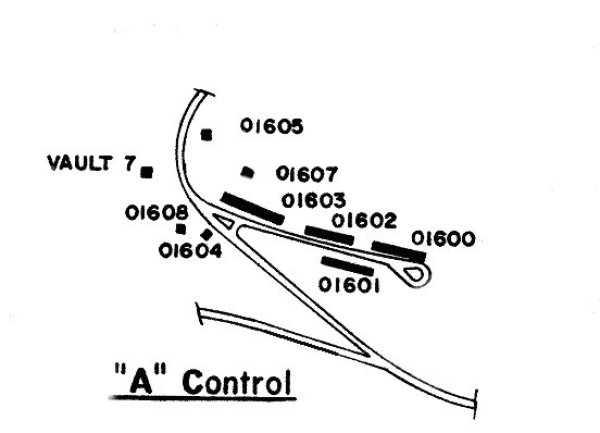
| Bldg # | Purpose | Year Demolished |
| 01600 | Unknown | Unknown |
| 01601 | Dining Hall Airmen | 1985 |
| 01602 | Dormitory Airmen | 1985 |
| 01603 | Administration Office | 1985 |
| 01604 | Electric Power Station Building | 1973 |
| 01605 | Guided Missile Autonavigator Facility | 1973 |
| 01607 | Guided Missile Autonavigator Facility | 1973 |
| 01608 | Guided Missile Autonavigator Facility | 1973 |
| Vault 7 | Unknown | Unknown |
The Integrated Fire Control (IFC) area was located on a hill or high place for best practical radar views of targets. At Thule, they were located on North and South Mountains. Because the earth is quite spherical ("round"), the higher you are above the surface of the sphere, the more surface and air above that surface you can see. The radar waves used by the Nike system travel in quite straight lines, like light. (Some other lower frequency radar waves have somewhat more complex possibilities.)
The Integrated Fire Control (IFC) area was surrounded by a stout fence, and guarded by armed troops. In general there was one gate (for the access road) through the fence, past the guardhouse. This was manned by an armed guard anytime the gate was open. Life, the international situation, and the troops were quite serious.
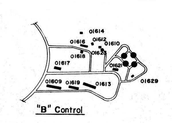
| Bldg # | Purpose | Year Demolished |
| 01609 | Dining Hall, Airmen | 1973 |
| 01610 | Guided Missile Autonavigator Facility | 1973 |
| 01612 | Guided Missile Autonavigator Facility | 1973 |
| 01613 | Dormitory, Airmen | 1973 |
| 01614 | Guided Missile Autonavigator Facility | 1973 |
| 01616 | Guided Missile Autonavigator Facility | 1978 |
| 01617 | Supply Issue Shop | 1973 |
| 01618 | Electric Power Station Building | 1973 |
| 01619 | Dormitory, Airmen | 1973 |
| 01621 | Electrical Power, Station Building | 1974 |
| 01623 | Storage check out and assembly | 1973 |
| 01629 | Storage check out and assembly | 1973 |
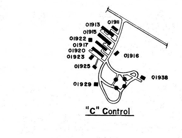
| Bldg # | Purpose | Year Demolished |
| 01911 | Supply Issue Shop | 1974 |
| 01913 | Dining Hall, Airmen | 1974 |
| 01915 | Dormitory, Airmen | 1974 |
| 01916 | Guided Missile Autonavigator Facility | 1973 |
| 01917 | Dormitory, Airmen | 1974 |
| 01920 | Guided Missile Autonavigator Facility | 1978 |
| 01922 | Guided Missile Autonavigator Facility | 1973 |
| 01923 | Electric Power Station Building | 1973 |
| 01925 | Guided Missile Autonavigator Facility | 1973 |
| 01929 | Storage, Rocket Check Out/Assembly | 1973 |
| 01938 | Storage, Rocket Check Out/Assembly | 1973 |
The Integrated Fire Control (IFC) area was connected to commercial power whenever practical, with converters to 400 hertz (cycles per second). This saved fuel, wear and tear and maintenance on generators and personnel. Most commercial power is 60 hertz (U.S.A) or 50 hertz (Europe). Special equipment is required to do this conversion - usually a 60 (or 50) hertz motor direct coupled to a 400 hertz generator. The Nike system was made as light as practical for easier transportability. Motors and transformers using 400 hertz (cycles per second) electricity are considerably lighter (need less iron) than similarly rated motors and transformers for 60 hertz. Also, 400 hertz is frequently used by the Army and Airforce in aircraft situations.
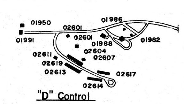
| Bldg # | Purpose | Year Demolished |
| 01950 | Airport Surveillance Radar AN/GPN-20 Active, not part of D-Control | |
| 01982 | Electric Power Station Building | 1973 |
| 01986 | Concrete pad for Equipment Demolished, not part of D-Control | |
| 01988 | Storage, Rocket Check Out/Assembly | 1972 |
| 01991 | LMR Transceiver Site Active, not part of D-Control | |
| 02601 | Guided Missile Autonavigator Facility | 1973 |
| 02604 | Guided Missile Autonavigator Facility | 1973 |
| 02607 | Guided Missile Autonavigator Facility | 1973 |
| 02611 | Electric Power Station Building | 1973 |
| 02613 | Dining Hall, Airmen | 1978 |
| 02614 | Dormitory, Airmen | 1978 |
| 02617 | Dormitory Airmen | 1978 |
| 02619 | Unknown | Unknown |
The Integrated Fire Control (IFC) area had electrical generating equipment and fuel, in case of alert or local power failure. In the case of an alert, both the launcher area and IFC area started their generator, and switched over to this power. The commercial power was subject to a number of possible situations such as normal outages, attack damage, or intentional disruption.
With the Nike Ajax, there were had two gasoline engine driven 40 kW generators, and an operator to watch them. A 40 KW generator fits well into a two wheel trailer, and is a little larger than the usual search light generator you see at store openings. An engine working at 40 horse power easily runs a generator running at 40 KW, even allowing for the usual generation losses. The Nike Hercules HIPAR radar and associated equipment increased the power requirement and those sites had larger generators enclosed in buildings.
The Integrated Fire Control (IFC) area had telephones and radios for communication with other site areas. There was a necessary link with the launcher area that provided the following necessary information:
- Alert status to launcher area
- Which Missile selected, from launcher area to missile tracking radar for automatic slew to next missile
- Azimuth Angle of predicted intercept point from computer to missile gyro
Launch (FIRE) command from FIRE switch, various safety interlocks, computer generated 2 second delay (for gyro settle) to launcher area.
These signals were normally transmitted automatically through the signal cable to the launcher area. In case of a cable fault, the signals could also be transmitted by voice radio and manually entered in at the launcher area. The missile selected could also be voice transmitted from launcher area to the IFC area and the missile tracking operator. Phone links to the administration area were useful for arranging transportation of relief crews and other day to day requirements.
The Integrated Fire Control (IFC) area had communication equipment for communication with tactical headquarters. Later there was sophisticated and effective control using: Missile Master, then BIRDIE and Missile Monitor by Tactical Headquarters.
The Army ADA batteries were always under the command and control of the Air Force by several means. Then came the Army command and control from the Army Air Defense Command Post (AADCP) at the battalion level. Communications may be lost with the Air Force but the battalion still had control of the site.
During the time of an air battle, a pilot could loose or forget to activate his IFF equipment. If so, there was only one safe way to return to any air base in any area. That was through the SAC-EWO safe corridors. The Strategic Air Command had predefined safe corridors back to any Air Base if the aircraft was having IFF or other problems. These corridors were zigzag lines (not straight lines) that the pilot had to follow and he had to be at certain altitudes at any given range to the air base. These safe corridors were marked on the PPI scopes in the fire control vans of HAWK and NIKE batteries. As long as an aircraft was in the corridor and heading in or out and at the proper altitude for the range he was at, he was safe without squawking the proper IFF code or no code at all. If there was an air battle going on at the time, most stray aircraft coming into range of a HAWK or NIKE battery would have been taken out, just because.
In Alaska the Air Force interceptors would have engaged any low flying aircraft. High flying bomber formations were at the pleasure of the NIKE batteries. The unofficial motto of ADA was to "shoot them all down and sort them out on the ground" and then send out letters of apologies.
The Integrated Fire Control (IFC) area had one or more surveillance radars for target identification. These are also called "acquisition" radars. In the original Nike Ajax sites, there was what is now called the LOPAR (for LOw Power Acquisition Radar) acquisition radar with a maximum display range of 100,000 yards or 56.8 miles. This was a "normal" magnetron pulse radar with a switchable moving target indicator (MTI) option.
Hercules sites (with the much longer missile range) needed a much longer-range surveillance radar. Two general types of longer-range surveillance radars were supplied:
1. the very large HIPAR radar that had a large control building. There was very sophisticated pulse generation, and multi-channel receivers with unique moving target indicators (MTI) and great deal of anti-jamming capability.
2. or a less sophisticated "Alternate Battery Acquisition Radar" (ABAR) radar usually either AN/FPS-69,-71 or -75.
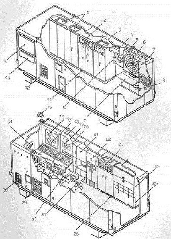
The Integrated Fire Control (IFC) area had radar(s) for target tracking (one target at a time). The BC van and RC van were inside the admin building and all the antennas were inside air inflated radomes with individual blowers.
The Nike Hercules used two Target Tracking Radars. One radar tracked the target in azimuth and elevation, in "X" (3 cm) band. The other radar (Target Ranging Radar) tracked the target in range, in several radar bands. Range jamming is easier than angle jamming, so great attention was paid to counter-acting the range jamming including band switching, very agile frequency changing, pulse blanking, and pulse repetition rate changing.
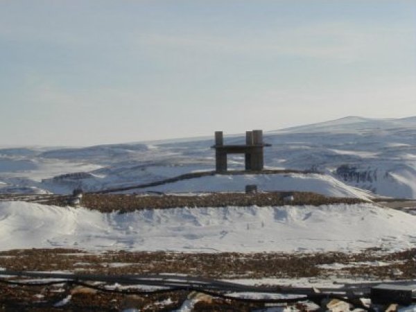
If present, the non-mobile HIPAR Surveillance radar always was on a tower, it was apparently part of the equipment. If the tower is a bare concrete pylon surrounded by an outer steel skeleton (square in plan view if you were looking straight down on the tower), then it''s an early tracking radar tower.
The Integrated Fire Control (IFC) area had a computer to aid target selection, aid launch timing, send missile commands. This computer received tracking inputs from the target and missile radars and provided the following:
- During pre-launch, while tracking the target, a Predicted Intercept Point and a Predicted Time of Flight was presented on plotting boards to the Battery Commander. This was based upon an assumed straight line flight. It was up to the Battery Commander to try to evaluate what the target would really do, and decide when and if to FIRE (launch a missile).
- After launch, all of the above were continuously updated for the Battery Commander, and the computer also sent guidance commands to the missile via the Missile Tracking Radar.
- The missile burst command, also via the Missile Tracking Radar.
The computer technology was "analog" instead of the digital technology, which was quite primitive and unreliable at that time.
The battery commander sat in the Battery Control van with:
- the acquisition operator(s)
- the computer and plotting boards, surveillance radar displays including the Identification Friend or Foe (IFF)
And was in direct communications contact with:
- the target tracking operator(s)
- the missile tracking operator
- the Launch Control Officer(s) in the launcher section(s)
- Tactical Headquarters
and operated the "FIRE" switch to control if and when to launch a missile
The missile tracking radar physically and electrically resembled the target tracking radar except for the dual transmit pulse capability. The missile tracking radar also transmitted the missile commands.
The Nike Hercules systems had two Target Tracking Radars that were externally similar. Internal differences included using different frequency bands. The two radars were used instead of the usual one radar to help fight enemy jamming. A variety of strategies made the life of enemy jammers extremely difficult. (The Nike Ajax systems had one target tracking radar).
One of the many keys to precision tracking between the target and missile tracking radars is the fact that (small) identical errors of tracking by both the target and missile tracking radars "cancel out". Example, if both the target and missile tracking radars say that their respective tracks are both 100 yards higher than absolute height, the actual miss distance (if every thing else was perfect) would be 0 yards.
This way, errors due to radar wave (like light wave) refraction in the atmosphere cancel out if both radars are tracking the same point in space (in this discussion we ignore the slightly different paths due to the slightly different physical location of the two radar.
Since the Nike Hercules had an "effective" range more than 3 times the Ajax, and a real range more than 4 times the Ajax, errors due to wind buffeting and similar errors could be 3 or 4 times larger, and possibly render Hercules ineffective (too inaccurate) at longer ranges.
To counter the wind buffeting, the tracking radars were enclosed in an air inflated fabric "bubble". This greatly reduced the wind forces on the tracking antennas. Even if the wind gust shifted the bubble a few inches, the air forces on the antennas would be greatly reduced during the shift of the "bubble". The "bubble" also protected the antenna from much of the differential heating due to the sun heating (expanding) one side of the mount and antenna relative to the other side (shady side) of the mount and antenna. Although both tracking antennas would likely be illuminated by the sun the same way, vertical alignment was usually made by one person at slightly different times (an error source) and one was never confident that everything was identical anyway.
The Integrated Fire Control (IFC) area had a radar alignment system for "bore sighting" the tracking radars. This was located about 200 yards away from the tracking antennas. The system included, a cable for remote control and power, a tall mast with supporting lines, a control box (1''x1.5''x1.5'') mounted on the mast, a waveguide up the mast, a little horn antenna and cross arm optical targets on the top of the mast. This was used primarily for boresighting the tracking radars. There was also provision for testing the radar receiving sensitivity.
The IFC Battery Control is where the Battery Commander and the Acquisition Operator sat. This was the central command place of the battery. Summations of the status of other places of the battery arrived here, and commands to battery components went out from here.
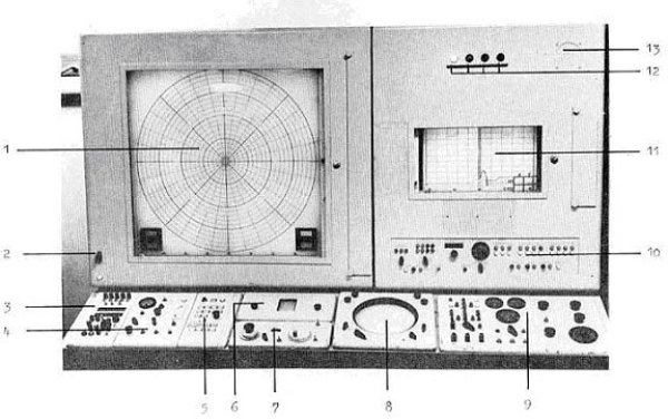
This is a diagram of the work place. The battery switchboard is just to the right, and the computer cabinets are to the right rear.
1. Plotting board, thin paper & ink, largest ring is 200,000 yds (over 110 miles)
2. T1 quick disconnect (T1 was a van that generated simulated aircraft echos and ECM interference for training purposes)
3. IFF (Identification Friend or Foe) control panel (the latest version with the Siemens IFF/SIF)
4. ACQ control panels - control the LOPAR radar
5. HIPAR control panel - control the HIPAR radar
6. Precision Indicator (PI) - (expanded view of the PPI -about 22 degrees wide 10,000 long)
7. Target Designator Panel - paints a ring and azimuth line to indicate designated target to Target Tracking operators - they see the same PPI picture)
8. Plan Position Indicator (PPI) ("radar scope") - also sent by the Target Tracking operators in the Radar Control van
9. Tactical control indicator
10. BCC indicator panel
11. Vertical plotting board 200 kyds / 100 kft
12. Status indicator lights, (White, Yellow, Red, Blue)
13. Target detected speaker (to help arouse sleepy operator)
The Integrated Fire Control (IFC) area had a computer to aid target selection, aid launch timing, send missile commands. This computer received tracking inputs from the target and missile radars and provided the following:
- During pre-launch, while tracking the target, a Predicted Intercept Point and a Predicted Time of Flight was presented on plotting boards to the Battery Commander. This was based upon an assumed straight line flight. It was up to the Battery Commander to try to evaluate what the target would really do, and decide when and if to FIRE (launch a missile).
- After launch, all of the above were continuously updated for the Battery Commander, and the computer also sent guidance commands to the missile via the Missile Tracking Radar.
- The missile burst command, also via the Missile Tracking Radar.
The computer technology was "analog" instead of the digital technology, which was quite primitive and unreliable at that time. In the 1950''s, digital computers had tens of thousands of vacuum tubes, and because the vacuum tubes had a mean time to failure of only a few thousand hours, the computers had a mean time to failure of only a few hours. 90 percent "up" time was considered outstanding, and required a round the clock staff of real experts. Digital input and output devices were similarly failure prone. (In the 1970s, when reliable transistors and integrated circuits, and cheaper high speed memory became available, some Nike analog computers were replaced by digital computers.)
The only alternative that was reliable enough and accurate enough was the electronic analog computer, which could be implemented for the Nike with fewer than 500 vacuum tubes. There were failures, but the technology was maturing, the tubes were run in a different (not ON/OFF) manner, and the uptime exceeded 99% at most sites. (One failure a month was considered really poor.)
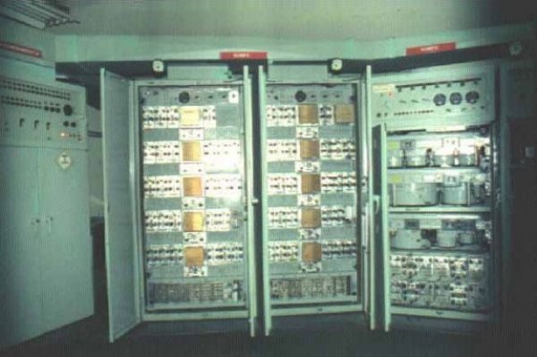
- Left rack has the power supplies - outputs about 7 different voltages. Top panel is switches, meters, voltage warning lights. (Note: in the van installation, this rack is on the right side of the computer.)
- Middle two racks - operational amplifies, brown square boxes are zero set units, back part of both racks have many relays
- Right rack has the servo-driven potentiometers. Top panel has tracking radar offsets, test switches (sets test inputs, verify outputs)
The Nike Computer had 4 main missions:
- Provide Pr